![]()
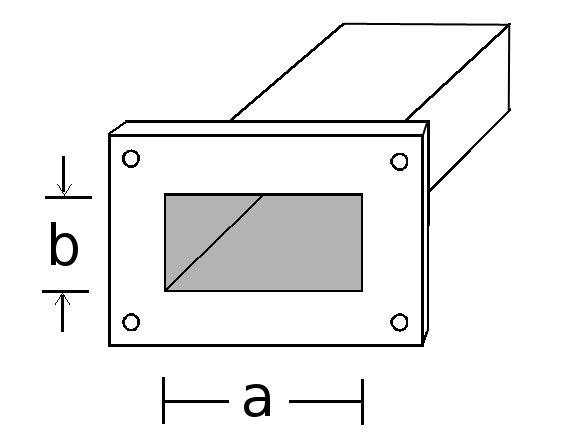
Rectangular waveguide is a very low loss transmission medium, that is mainly used above a few GHz, since the size of waveguide is very large at low frequencies. The internal width needs to be at least half a wavelength. So at 1 GHz, where the wavelength is approximately 300 mm, the internal width of the waveguide needs to be more than 150 mm. As such, except for a few specialist applications, waveguide is not used below a few GHz. WR2300 waveguide, which has an internal width of 584.2 mm (24") and height of 292.1 mm (11.5") is used between 320 MHz and 450 MHz, but it is rarely used. For more information about waveguide, see the Microwave101.com website or the everythingRF website
For coaxial connectors, short, open and load calibration standards are normally used. The ideal properties of these are:
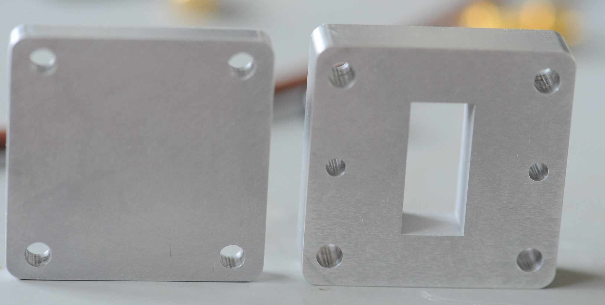
It is possible to make very good waveguide loads, and a waveguide short is easy to make too. The left hand object in the photograph below is used to create a short across the waveguide.
Unfortunately, it is impossible to make any waveguide device that acts like an open in a coaxial calibration kit. Leaving the waveguide open, will cause the waveguide to radiate, making an antenna, with a return loss of about 13 dB, although it changed across the frequency range. Some simulations performed with HFSS on WR90 waveguide can be found in a paper Rectangular waveguide radiator miniaturization using electromagnetic infinity-shaped metamaterial resonator. Although at the waveguide cutoff frequency all power is reflected, through the frequency range of normal use, the return loss is around 13 dB. Since most power is radiated, an open-ended waveguide is not suitable as a VNA calibration standard.
The get around this problem, an offset short is used in waveguide calibration. A spacer which is a quarter wave (λ/4) is added to the waveguide, and then the short attached. The electromagnetic radiation reflects off the short, but since it has twice passed though the (λ/4) the phase has been delayed by 180°, which meets the requirements specified earlier, that the difference in phase between ttwo calibration standards should be close to 180°. Due to the fact that the wavelength in waveguide is not a simple function of frequency, in practice the phase difference between the two reflection standards will vary significantly across the waveguide band. However, this variation can be calculated by the VNA, and is not sufficient to cause problems.
The steps to perform a waveguide calibration are depend on whether a one port or two port calibration is required.
That completes a 1-port waveguide calibration on a VNA
The steps are similar to above, but with some differences.
There are a number of variations of this method, such as using a load, then a load with a spacer, to make an offset load, or TRL calibration of waveguide.
Kirkby Microwave Ltd is registered in England and Wales, company number 08914892. Registered office: Stokes Hall Lodge, Burnham Rd, Althorne, Essex, CM3 6DT.